Introduction
The Electromagnetic Spectrum (EMS) comprises the span of all electromagnetic radiation, which is divided into many sub-ranges and separate frequency bands due to their different physical properties. The Electromagnetic Environment (EME) is the geophysical environment, influenced by such factors as terrain, weather and atmospheric conditions, which supports the radiation, propagation, and reception of electromagnetic energy across the entire EMS. To put it simply, the EME is the physical realm which bridges all warfare domains of operation,1 including Unmanned Aircraft Systems (UAS). Since most UAS depend on the EMS in order to operate, degrading or denying their use of the EMS has the potential to prevent many UAS from conducting effective operations. Electronic Warfare (EW), the traditional warfighting element of the EME, has been rapidly expanding its capability to include advanced and joint Electromagnetic Operations (EMO) in the EME. This article will discuss how UAS operations could be countered through EMO, concentrating on detection, classification, and engagement.
Detecting and Classifying Unmanned Aircraft Systems
Especially considering the emerging technologies in Low, Small, and Slow (LSS) UAS, detecting and classifying UAS and drones has never been more challenging or critical. Features such as very low Radar Cross Section (RCS)2 and difficult discernibility in many other spectrums, along with very low flight altitudes and slow speeds can combine to present extremely difficult environments in which to detect these threats. The two ways of detecting UAS using the EMS is through active and passive systems. The main difference between the two is that an active system sends out a signal, and the return signal is analyzed. For passive detection, the detecting system remains silent on the EMS and uses active or passive emissions from the target for analysis.
The active and passive detection and classification techniques that should be considered to accomplish this task are discussed in the following section.
Active UAS detection
Radio Detection and Ranging (Radar) sensors are currently NATO’s main option for active air surveillance, target tracking and potentially subsequent engagement guidance. Active radar systems emit Radio Frequency (RF) signals and analyze the backscattered energy from a potential target. Hereby, the architecture, composition and used frequency of a radar is dependent on the use case and the anticipated targets. Different frequencies have different properties like range, resolution, atmospheric attenuation or accuracy. Very low frequencies could be used for ‘Over-the-Horizon’ or ‘Anti-Stealth’ detection, but the respective systems tend to be quite large, and their resolution is significantly lower than systems radiating at higher frequencies. On the other hand, very high-frequency micro-wave radar systems have an outstanding resolution and accuracy even for very small targets, but have only a very limited range due to atmospheric attenuation. Therefore, most radar systems are designed for a specific purpose in accordance with the anticipated target load and the necessary track quality and a ‘One-Size-fits-All’ solution does currently not exist.
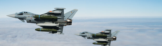
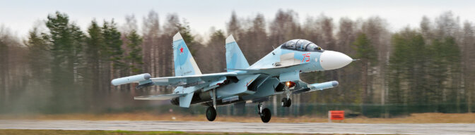
Radar systems have evolved quite a lot since their inception in 1886 by Heinrich Hertz and they are capable of tracking a wide array of aircraft, satellites or ballistic missiles. To see, how capable existing systems are in coping with Unmanned Aircraft (UA) and drones, they need to be compared to the target types already covered by these systems. In general, four factors primarily influence a radar’s capability of detection, namely RCS, altitude, range and speed. The RCS describes the anticipated RF energy reflection of an object from a certain angle and in a certain frequency. When the RCS is large enough to produce an evaluable signal to noise ratio for a sensor, the object is detectable. It needs to be able to distinguish between naturally small RCS (e.g. micro UA) and artificially shrunk RCS like in stealth aircraft (e.g. F-35). The use of low frequencies might help to discover stealth aircraft, but they might not have the resolution and accuracy to detect a small Class I UA or drone. In this case, higher frequencies in the upper centimetre or even millimetre-wave regime can be beneficial. The wavelength specifications need to support the target detection requirements. Once the right frequencies are identified, the signal needs to be optimized for the target as well. Signal length, pulse composition or pulse compression are just a few parameters or techniques to support detection and tracking.3 Some target parameters can be identified by analysing changes within the return signal itself. The well-known Doppler Effect can be used to identify the relative velocity of a target towards the sensor since the frequency of the return signal will be shifted accordingly. However, the Micro-Doppler Effect will cause an effect on the return signal due to micro-vibrations or movements of the target. For example, rotor motion can be picked up and analyzed to identify UA and drones and distinguish them from other unwanted targets like birds. This functionality is frequency-dependent, so for very small intra-target motions, high-frequency sensors are needed.4
The following figure is a general comparison of RCS from UA and drones with other objects. It shows that a typical Medium-Altitude Long-Endurance (MALE) UAS has an RCS similar to existing fighter aircraft.
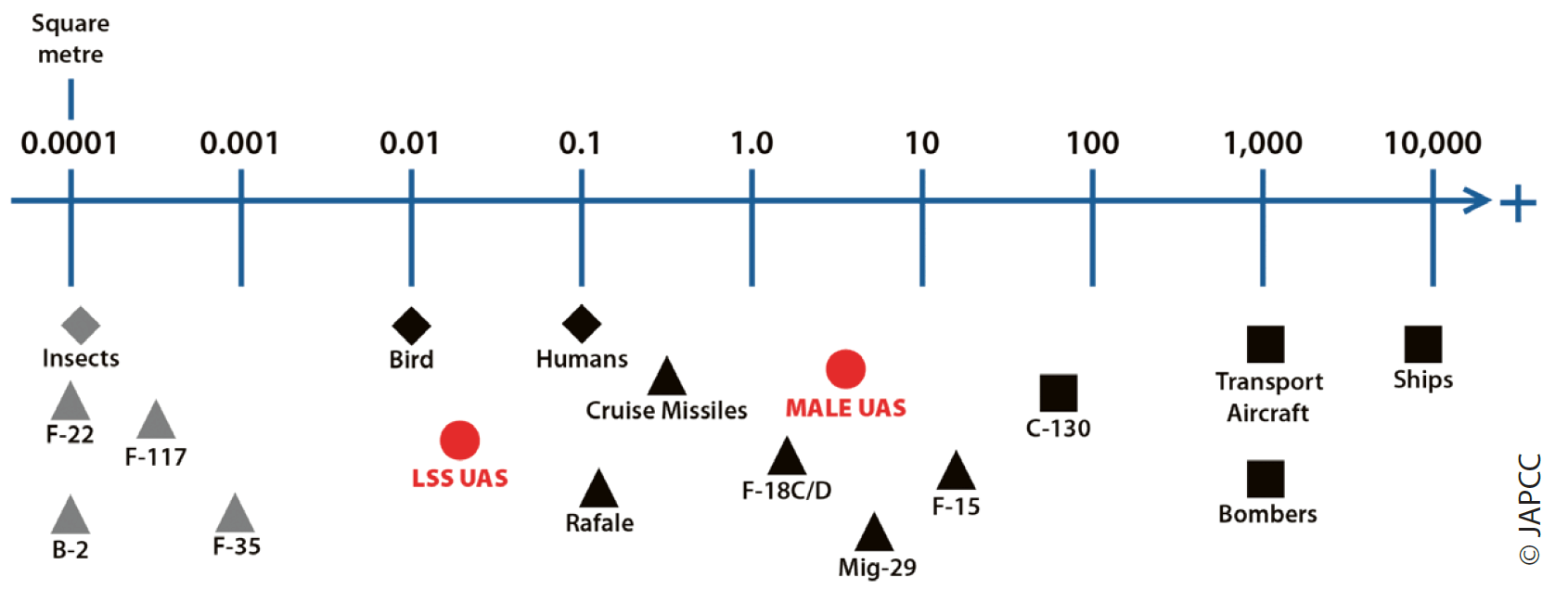
With the radar sensor as the constant in this equation, it can be assumed that the smaller the RCS of an object, the closer it needs to get to the receiver to produce a usable return signal or the more RF energy that needs to be radiated. RF energy output of all systems is limited, so the distance becomes the variable. The detection distance may become even less due to the potentially very low flight paths of small UA and drones, which prevents a line of sight detection independent of the RCS. The short detection range makes these threats a high risk for NATO in general, and it becomes amplified with the employment of small UA and drones in swarms or with high levels of automation.
Most air surveillance/defence sensors are designed to cover very large volumes of airspace in a threat optimized fashion. This means that sub-volumes with a higher likelihood of target presence will be looked at more frequently to increase the probability of detection. This is normally prioritized by the threat/risk-level of the targets, in order for the highly threatening objects to be detected first. Large Class II or Class III UA can easily be incorporated in this calculation and the available sensor mix should suffice. Smaller UA and drones are not only highly threatening but also especially challenging due to their late detection and short engagement distances. Several facts make it infeasible to incorporate these targets into the load for a large volume sensor:
• Every air defence radar has a minimum distance for detection, which might be longer than the UA distance to the sensor.
• A concentration of radar dwell time in the anticipated Class I UA airspace volume will negatively impact the radar’s performance in its originally anticipated mission.
• A longer-range sensor might be capable of sensing small UA that pose a risk to itself, but may be challenged to provide coverage for extended self-defence of other entities, due to terrain feature coverage.
This leads to the circumstance that, as with any other air target, an appropriate sensor for the threat has to be identified and most likely this network of various sensors will bring benefits as well. The sensor has to satisfy at least the following needs:
• Cover the target-specific range and altitude band.
• Provide sufficient update rate and accuracy.
• Provide sufficient agility for the mission.
Next to radar sensors using RF signals, other wavelengths of the EMS are being looked at for ‘ranging and detection’. In addition to radar, Light Detection and Ranging (LiDAR) can be used for distance, angular and speed measurements of distant objects. LiDAR sensors are often used for 3D mapping of the environment but have also found their way into automation applications, like unmanned cars. Due to their high accuracy and fast update rates, their application in the detection and tracking of small UA and drones is being researched.5
Passive UAS Detection
Aside from active detection, where an artificially produced signal is being used and the return analyzed, there are passive options for detection and tracking. Here, the active and passive EMS signatures of an object are used for further processing. The most obvious option is to use deliberate RF emissions like data links, voice-radio emissions or onboard radar sensors. These signals are meant to be received by a dedicated system, so the signal is strong enough to cover relatively large distances. However, every system that is using electronic circuits has a noticeable EMS signature. Here, the unintentional transmission output is far lower, so it cannot be received over large distances. A third option is to basically use a variant of a bi- or multi-static sensor, so-called passive coherent location radars.6 In this case, the receiver uses target backscatter from unrelated, but known emitters (e.g. television broadcasting, cellular networks or radio stations) as the source of analysis. Since all of these capabilities are mostly based on the concept of triangulation, arrays of passive sensors are needed for this concept to work. In all three cases, adversary systems can install measures to reduce the applicability of passive detection. Internal circuits can be shielded, so their unwanted transmissions are minimized. RF absorbing coatings or RF energy scattering designs can be used, which are nearly impossible for lower frequency bands. The onboard transmitter can have a very high directionality, with minimized side-lobes, use strong frequency agility/diversity or use very high frequencies that get attenuated by the atmosphere more quickly. However, all these options are more likely to be found in Class III UAS and not the small Class I size or drones. In general, higher levels of automation reduce the need for RF links to a control station, which impedes passive detection as well. Despite these possible countermeasures, the passive detection of Class I or small Class II targets or low RCS Class III UA is a plausible alternative or augmentation to active detection, especially since larger active sensors have weaknesses in short distance detection.
In addition, fielding friendly passive C-UAS detection systems provide excellent concealment against detection by opposing Electronic Support Measures (ESM). Since these friendly passive radars are not emitting energy, they cannot be detected and targeted by EW and SEADi aircraft or UAVs (such as the Israeli ‘Harpy’ or ‘Harop’ UAS). Aside from being highly mobile and detecting small or stealthy UA, passive radars can operate in congested EM environments such as urban centres where adversaries will likely employ such UAS.
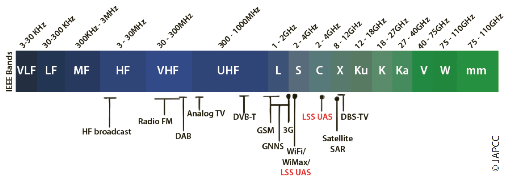
RF analyzers can be used to identify the frequency of a specific RF transmission or follow complex frequency hopping patterns. These analyzers can detect the control or video signals over the RF (including Wi-Fiii or cell phone signals) employed for UAS operations and can be easily carried on mobile platforms. Once the dedicated frequencies are identified, the controller and drone locations (when actively emitting) can be triangulated by the aforementioned passive radar systems. RF analyzers are a valuable tool to support passive detection of Class I UAS. However, the effectiveness of analyzers can be reduced in highly congested RF environments due to saturation.
Passive sensors and RF analyzers are typical tools in support of ESM. This is the traditional military discipline of EW within the reconnaissance and surveillance systems, to sense and passively collect EM emissions and information to detect, locate, identify, record and analyze radiated EM energy for threat recognition and long-term operational planning. ESM information can be assessed through intelligence products such as Signals Intelligence (SIGINT), Communications Intelligence (COMINT) and Electronic Intelligence (ELINT). Consequently, this EW function may report the detection of UAS EMS emissions and could contribute to the generation of an Electronic Order of Battle (EOB), which usually includes critical electronic information on threats depicting the likely locations of UAS components such as ground stations. ESM is not usually producing real-time data, but it is a good source in support of C-UAS real-time operations. Technological advancements have promoted the evolution of tools such as CESMO7 (Cooperative ESM Operations) that can triangulate and share electronic emitter information within networks almost in real-time and increase the opportunities for UAS detection and C-UAS operations.
Electro-Optic and Infrared (EO/IR). A promising passive method of UAS detection is through the use of Electro-Optic (EO) and Infrared (IR) light sensors. EO includes the visible light and Ultraviolet (UV) light spectrum of wavelengths. The spectrum of these three wavelengths is shown in Figure 10.3.
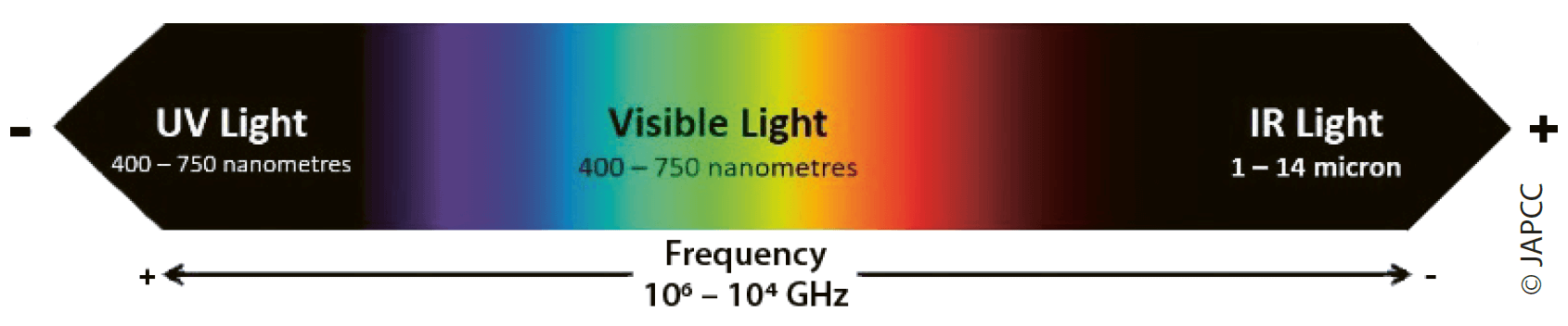
The detectability and classification of objects through the use of systems utilizing these wavelengths is highly dependent on the reflectivity and emissivity of the object compared to the apparent background, including environmental effects. The designed function of the system will often determine what spectral band is best to achieve detection. For instance, if an object is flying in an environment with little visible and UV light present (such as during the night), IR sensors may be the best solution to trace the IR radiation (heat) emitted by the UA.8 By contrast, in environments with ample visible light and UV present (such as during the day), EO sensors may be more suited for detection and classification, depending on many variables. Since reflectivity and emissivity of a material changes based on the wavelength of energy being analyzed, the environmental conditions greatly affect wavelength transmission.9 The use of multi-spectral sensors that can fuse UV, IR, and visible light has great potential to detect UA across a wide range of conditions.
Night Vision Devices & Low Light Cameras. These systems primarily collect ambient visible light and intensify the image by using photocathode technology to produce electrons from the photons in the incident light. They may also integrate IR illuminators to increase their range for detection and classification, making them both a passive and an active system. If the object is emitting or reflecting even a small amount of energy in the visual spectrum, these systems have great potential to be an effective method of detecting UAS at considerable ranges. However, since these low light systems operate with visible light, they have poor performance in twilight conditions and are negatively affected by environments with high humidity, fog or smoke, not unlike other EO systems.
Acoustic Detection
In addition to the IR and EO spectrums, the noise produced by UA can be detected. Microphone arrays can be deployed to detect sound waves and triangulate the origin of the acoustic emission. However, detection ranges of acoustic sensors are very limited and may only support detection of Class I UAS and drones.
Chapter 4 (cf. p. 58 ff.) discusses the acoustic detectability of UA in more detail. Depending on the background noise, detection ranges vary greatly and can be expected to range up to 1,000 m in a quiet rural area, but are limited to only a few hundred meters in a noisier urban environment.
Action Against UAS Within EMS Context
Once the UAS is detected and classified with enough fidelity to determine the appropriate response, effects will need to be applied to the UAS to meet the commander’s intent. This section will discuss the many ways EMO can be used to affect an UAS.
Active and Non-lethal EW Actions Against UAS
Traditional active measures for EW are jamming and deception10 of the signal for UAS control. For jamming, a large enough amount of RF energy (in the previously identified frequency, frequency spectrum or frequency sets) is directed towards the UA’s receiving antenna to mask the UAS RF control or data signals. Hence UAS operations are likely the target for denial or disruption. Deception is more complex since it is target and even content-sensitive. Therefore, more information than just the operating frequencies is needed. A signal with a new or altered content to manipulate UAS behaviour gets fed into the UA or control station to interfere with the UAS’ mission. Terms like spoofingiii or meaconingiv are being used in this context as well. The advent of UAS has accelerated the development of portable or mobile special jamming/deception systems to counter drones by neutralizing them through EW techniques. Jamming and deception can be done reactively, but also pre-emptively, for example by flooding the anticipated frequencies with RF noise, emitting altered GPSv signals or spoofing/hijacking cell tower signals. Such jamming/deception modules can be installed on existing infrastructure like cellular network antennas which would affect UAS signals within a wide geographic area and particularly where UAS Class I and II are likely to operate. These are non-kinetic solutions, which work effectively at close distances against Class I and II UAS rather than Class III UAS that are typically flying at higher altitudes.
Directed Energy Weapons
Although research in the field of lasers for use in military applications has been conducted for over 50 years11, only recently have laser systems been able to be used to counter air threats such as UAS. Directed Energy Weapons (DEW) systems are designed to provide a focused beam of energy in order to disable or disrupt the target. DEW defensive systems have many possible advantages to traditional kinetic systems, including the capability to perform speed of light engagements, the ability to adjust output energy, the access to potentially unlimited number of shots (limitless magazine), and cost savings when compared to many traditional systems. DEW systems are already being employed for C-UAS on ships and surface vehicles.12 The primary DEW weapons being employed are discussed next.
High Energy Lasers. Since lasers designed to cause blindness in humans were banned by the United Nations in 1995,13 military lasers have primarily been used to provide precise targeting information to guided munitions and ‘dazzle’ targets for incoming IR-guided munitions. High Energy Lasers (HEL) have had little success until fairly recently due to rapid technology improvements, whereas having to counter LSS UA was one of the main driving factors for these developments.14 There are currently multiple HEL systems being deployed by NATO members to combat zones to determine their efficacy in combating small UA.15 Systems fielded by the US Air Force, Army, Navy, and Marine Corps have all had broad success in the C-UAS mission during recent ‘real-world’ trials.16 These trials bode well for the future of HEL to fill the critical role to counter LSS UA now, with larger HEL weapons systems being developed to have increased ranges to counter much larger and capable UA (in addition to other targets).17
Electro-Magnetic Pulse and High-Power Microwaves. These types of weapons are capable of disabling or destroying electronic components inside a UAS, instead of hitting the surface of the object with a laser. Electro-Magnetic Pulse (EMP) weapons can be delivered to disrupt radio links and the electronic circuits of the UAS. Even though EMP technology is not yet fully mature, it has been added to many C-UAS systems as another means to provide non-kinetic C-UAS effects.18 One of the primary benefits of EMP is that it has great potential to be used to counter swarm attacks, in addition to being employed with more focus at individual threats. When focused, it also has good potential to be employed at farther ranges than traditional HEL weapons, however, EMP weapons must be thoroughly tested and employed very carefully since they have the potential to cause significant collateral damage to friendly electronic assets, as well.
Passive EW Actions Against UAS
Passive defence, i.e. the mitigation of radiation propagation throughout the EMS should always be an integral part of countering UAS. It may encompass long-established techniques such as camouflage, sheltering or radio discipline to avoid being detected by an airborne sensor. Chapter 15 (cf. p. 269 ff.) discusses these measures in more detail.
Summary
The combination of UAS features, that may include a wide range of physical sizes, types of missions and payloads, including potential for swarming and full autonomy, lead to the conclusion that there is no single defence method able to counter all classes of UAS. Due to these vast differences, a multi-layered, tailorable, overlapping array of sensors and effectors is required. Mobility, weather and light conditions, network capacity and availability, atmospheric attenuation, the battlespace environment, and technological advancements are all paramount considerations that need to be properly planned to ensure the effectiveness of these sensors and effectors. The challenge of implementing this multi-layered Counter-UAS system of systems array is creating a command and control system able to merge the vast amount of incoming data to present a clear and accurate picture enabling the employment of the most appropriate UAS countermeasures. Managing and controlling sensor data collection through artificial intelligence applications may significantly contribute to creating an adaptable and effective UAS kill chain. Once a UAS is sensed by the network of sensors, an artificial intelligence application could task sensors in the area to gather the needed information to classify the system and then either provide recommended actions to a human response centre or operate autonomously to neutralize the threat.