Overview
Unmanned Aircraft share basically the same vulnerabilities as manned aircraft. However, it is not only the UA which can be subject to countermeasures. Each individual component of an Unmanned Aircraft System (UAS) has unique vulnerabilities and could be targeted to counter the UAS threat. This chapter describes the different system components, their limitations and vulnerabilities, as well as potential countermeasures against them. The countermeasures themselves will then be discussed in the respective subsequent chapters of this book.
Unmanned Aircraft
General Characteristics
Unmanned Aircraft is the overall term for all aircraft that do not carry a human operator and are operated remotely using varying levels of automated functions.1 However, the prevalent terminology in the civilian domain is ‘drone’, which is almost always used for the respective consumer and commercial UA variants. For the purpose of distinction, this chapter will use the terms ‘Unmanned Aircraft’ (UA) and ‘Unmanned Aircraft System’ (UAS) to indicate military-grade systems, and ‘drone’ for commercial or consumer products.
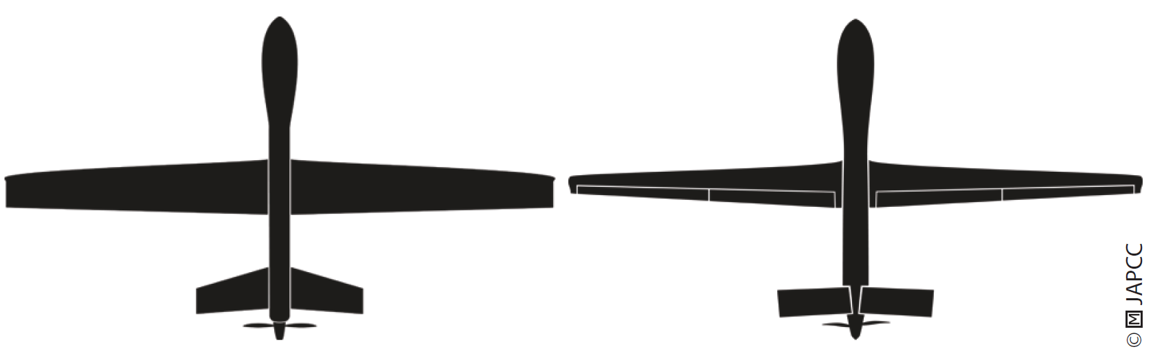
Unmanned Aircraft. Most of the current UA share design principles that seek to optimize long endurance and low fuel consumption. The most prominent features are wings with a very high aspect ratio combined with a rear-mounted, fuel-efficient propeller engine. Together, these provide the desired flight characteristics, but also bring with them certain disadvantages. High aspect ratio wings have a fairly high amount of inertia preventing UA from conducting flight manoeuvres with a high roll angular acceleration and G-force.2 Additionally, the average cruising speed of propeller-driven UA is quite low, e.g. 60 knots for the Russian ‘Forpost’ or estimated 80 knots for the Chinese Wing Loong.3, 4 Therefore, the UA is unable to conduct ‘last-ditch’ manoeuvres and becomes a rigid target compared to manned fighter aircraft.
Drones. Smaller systems are typically rotorcraft which feature four or more propellers to keep them airborne. This design allows for easy take-off and landing, lower airspeeds, and hovering the drone in mid-air. Together with an easy to use remote control, e.g. a mobile phone or tablet computer application, this design enables consumers such as hobbyists, farmers or photographers to operate drones with ease and without the detailed knowledge and airmanship military UAS require. Drones are generally susceptible to weather conditions, especially strong winds, due to their lightweight and size. However, their size and weight make them also highly agile compared to fixed-wing UAS.
Visibility to Radar Systems
The visibility of an object to a radar system is measured by the Radar Cross Section (RCS). RCS is defined as the measure of a target’s radar signal reflectivity in the direction of the radar receiver.5, 6
Unmanned Aircraft. Larger UAS like the Wing Loong, an almost exact replica of the MQ-1 Predator design, can be expected to display an average RCS of slightly less than one square meter which is comparable to non-stealth fighter aircraft.7, 8, 9 Although prototypes such as the Russian Okhotnik seemingly incorporate stealth technology, the vast majority of current systems lack any of these features.
Drones. In contrast to UAS, the radar reflectivity of drones is relatively low. Due to their small size, the majority of plastic components and generally lower operating altitude, they challenge most traditional air surveillance radars.
Visibility in the Infrared Spectrum
Hot engine parts, exhaust plumes, the rear fuselage area, and aerodynamically heated skin are the key sources of aircraft infrared (IR) emissions. In general, aircraft with a jet engine have the highest IR intensity.10
Unmanned Aircraft. The majority of UAS configurations have a turboprop engine fitted to the back of the UA, dispersing the exhaust through the pusher propeller. Compared to a turbojet-powered aircraft, this design results in a much lower IR signature. However, UAS are not necessarily resistant to attacks by IR-guided missiles. Modern IR-detection technology with its increased sensitivity is capable of detecting IR radiation in a wide enough spectrum to spot lower IR signatures from UAS.11, 12
Drones have very low IR emissions due to their typically battery-powered propulsion. However, most objects have a different temperature than the environment they are operating in. Therefore, thermal imaging will most likely reveal the presence of a drone,13 although not at the longer distance where a hot engine exhaust can be detected. The very low IR signature may also be not sufficient for an IR-guided missile.
Acoustic Detectability
Propeller noise can be measured by ground-based stationary microphones which use the Doppler Effect in the acoustic spectrum to compute an aircraft’s altitude, speed and actual revolutions per minute of the engine. Real-time computations on such signals can provide the direction or location of the sound source.14
Unmanned Aircraft. Many UAS are propeller-driven and generate a significant amount of noise. Depending on their altitude, the noise emissions can be so strong, the propeller noise alone may attract the attention of ground personnel.15, 16 However, UAS operating at higher altitudes are typically no longer audible for humans and require dedicated acoustic sensors to be detected.
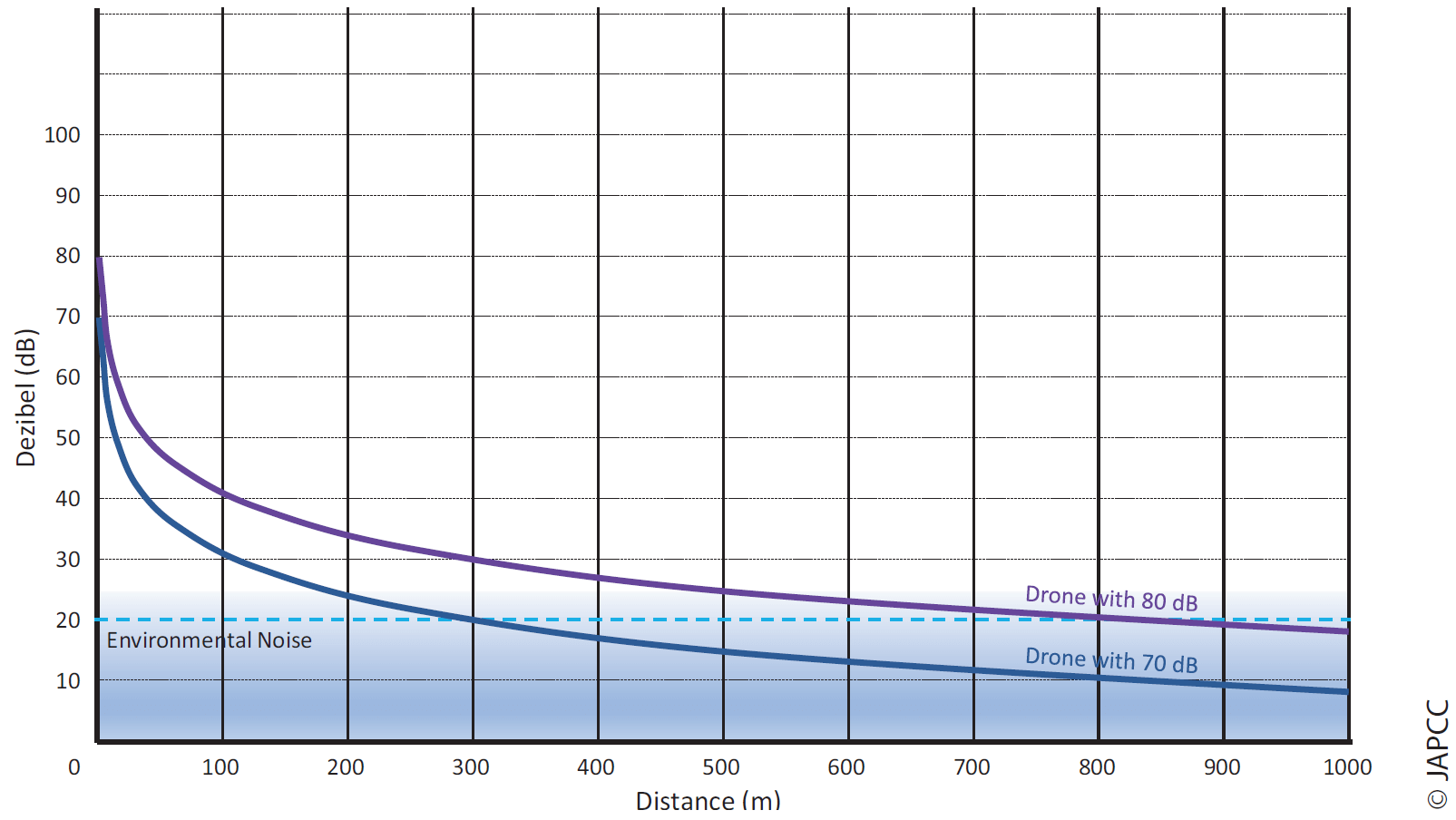
Drones emit significantly less noise than a UAS equipped with a turboprop engine. However, the noise level is still loud enough to be audible at shorter distances. The typical sound level of a consumer drone is between 70 dB and 80 dB, measured at a distance of one metre. This is comparable to a motorized lawnmower. If the distance to a sound source is doubled, the sound pressure level drops by 6 dB. Figure 4.2 shows this formula applied and how the noise level will fall below the threshold of 20 dB at a distance of approximately 350 m for the 70 dB drone and 1,000 m for the 80 dB drone, which means that the average environmental noise in a quiet rural area will be loud enough to mask the remaining noise of the drone.17, 18
Visual Recognition
The range at which aircraft can be detected, recognized and identified varies with the size, shape and colour of the aircraft, viewing aspect, visibility conditions, its motion relative to and contrast with the background and eventually, the visual acuity of the observer. Depending on these factors, the aircraft can be seen at long ranges in clear weather. When there is rain, snow, fog, dust or haze, the visibility range may be reduced to zero.19, 20
Unmanned Aircraft. The largest distance at which an aircraft can be seen by the human eye can be mathematically predicted from its size and contrast to the background. Given a perfect black & white contrast, an MQ-9 Reaper sized UAS, like the Wing Loong II, can be visually detected at a distance of almost 10 km, whereas lowering the contrast to 50 % reduces the detection range to roughly half. As military aircraft are typically camouflaged or painted grey to blend in with the surrounding sky, it can be assessed that visual detection of UAS without electro-optical support is limited to ranges of less than 5 km and is unlikely at altitudes above 15,000 ft.21
Drones. The challenge with visual detection of drones is their small size and discriminating them from different moving objects such as birds or even a plastic bag caught in the wind. It is most likely, that a drone will be heard before it will be spotted and typically the noise of a nearby drone is the trigger for visual recognition.
Payload
UA and drone payloads consist primarily of imaging sensors and – if applicable – a set of weapons. Payloads also have vulnerabilities, or better labelled ‘limitations’, which can be exploited too, for example, disrupting sensors, or misdirecting the UA’s weapons.
Sensors
Every sensor has specific characteristics of how it perceives its environment and how it processes that input into a human-readable output. The sensor input is typically limited to a certain type of radiation and its respective wavelength. Disrupting a sensor requires either masking the specific wavelength or using the same wavelength against the sensor to inject false information or blind it.
Chapter 3 (cf. p. 41 ff.) outlines the most prevalent types of UAS sensors and their specific characteristics. Most of the time, it might be more favourable to mask a certain range of wavelengths than to blind the sensor as active countermeasures may draw unwanted attention from the UA or drone. Traditional measures such as camouflage, light discipline, or dispersion of troops may be sufficient to counter an electro-optical camera. Reportedly, the Taliban in Afghanistan mitigated their risk of detection by US Predator and Reaper UAS by simply parking their trucks below trees and covering them with mattresses to suppress IR radiation from the hot engine. More sophisticated sensors, e.g. LIDAR or SAR, definitely require more complex countermeasures to reflect or absorb radiation in their sensing spectrum.
Weapons
UAS can basically carry every type of air-to-air and air-to-ground ordnance, limited only by its Size, Weight, and Power (SWaP) restrictions. It should go without saying that countering a weapon should be the very last option in the overall C-UAS approach.
Modern weaponry is typically guided by some precision enhancing method (Global Positioning System (GPS), internal Inertial Navigation System (INS) or Laser spot tracking). Terminal guidance can be based on imagery, light radiation (IR, Laser), or radar reflections. In general, the same principles about radiation and wavelengths as discussed in the sensor section above apply to guided weapons as well. However, a more active approach is required to misdirect an already released weapon. Laser and radar guidance require clear reflections from their intended target to hit accurately. IR guidance also requires a sufficient contrast between the IR source and its environment. Scattering or delaying reflections in the respective spectrum may induce significant enough error to the guidance system so that the weapon would miss the intended target.
Satellite-aided inertial-guided ammunition utilizes the Position, Navigation, and Timing (PNT) signals provided by at least one of the three respective satellite constellations, i.e. GPS (USA), GLONASS (RUS), and BEIDOU (CHN). The weaknesses and limitations of these systems will be discussed in more detail in Chapter 12 (cf. p. 209 ff.).
Every ordnance, guided as well as unguided, is susceptible to reflecting radar emissions and has a unique trajectory which is clearly distinguishable from natural objects. Depending on their amount of metal components and overall size, radar reflections may be quite low. However, these reflections are still above any LSS drone, and their speed and trajectory can help defenders in discriminating them from the environment and to detect the imminent threat.
Stand-off Limitations
The maximum functional distance of an imagery sensor, and in turn the UA, depends on the operational requirements of the
desired target resolution. A higher target resolution requires a smaller Ground Resolved Distance (GRD), which is, simply put, the smallest surface area a single image pixel can display. The GRD should be at least half of the size of the smallest detail which is required to be measured for the mission. For example, when trying to detect (not identify) persons on the ground, the GRD should be no larger than half of the width of the human body, which equates to roughly 40 cm per pixel.22, 23 This resolution can be achieved by even legacy cameras at distances of roughly 55,000 ft.24 However, the average operational altitude of MALE UAS is in the range of 20,000 ft to 25,000 ft to provide sufficient GRD for positive target identification,25 and, depending on haze, dust and other vision-obscuring conditions, the effective range can be even considerably lower.
The maximum range of non-propelled ammunitions, such as guided or unguided bombs, depends exclusively on the airspeed and altitude of the delivery platform. Current propeller-driven MALE UAS have a maximum speed of about 200 kts.26 Modern manned fighter aircraft are capable of bomb releases at high sub-sonic or even supersonic speeds and higher altitudes. The total potential (altitude) and kinetic (airspeed) energy of the weapon at release are the main contributors to its maximum range. Consequently, the same type of non-propelled ammunition will have a shorter range if released from a UA than if released from a manned fighter aircraft.
Limited Situational Awareness
The UAS’ sensors are the only direct source of information to build situational awareness. Although the sensor suite can take a very detailed look at a very small area, the viewer has no awareness of anything outside the ‘soda straw’ field of view of the aircraft’s
sensors. Boresight cameras mounted on the UA’s nose or tail provide the crew with a broader view of the flight direction, but they still do not receive the kind of cues they get from their proprioceptive senses.27, 28, 29
Additionally, UAS sensors are generally not designed for threat detection. In conjunction with the overall limited situational awareness, this is a fundamental vulnerability. The typical mission sets for ISR UAS in the relatively benign environments of the last decade have led to a focus on the improvement of sensor payloads rather than on the development of self-protection capabilities.30 Although self-protection suites used on manned aircraft are available, few, if any, UAS are currently equipped with them.
Human Element
Although the UA itself does not carry a human crew, there are a lot of personnel involved in the operation of UAS. Hence, attacking the personnel rather than the UA itself may also be a favourable option. UAS personnel can be classified into three categories: The Launch and Recovery Unit (LRU), the Mission Control Element (MCE) and the Processing, Exploitation, and Dissemination (PED) element.
Launch and Recovery Unit
Depending on the UA’s effective range, the LRU usually has to be located into or near the Area of Operations (AOO). For smaller UAS, the LRU is most likely deployed inside the AOO. For larger HALE and MALE systems with higher effective ranges and airspeeds, the LRU may be deployed to a neighbouring host nation. Launching and recovering UA requires a Line of Sight (LOS) data
link from a local Ground Control Station (GCS) and suitable airport infrastructure with a decent sized runway. Like for any other military aircraft, additional personnel for refuelling, arming and performing maintenance are needed as well. This infrastructure is likely to be well defended; however, a successful attack on an LRU will disrupt any UAS operations significantly.
Mission Control Element
Larger military UAS are typically capable of operating Beyond Line of Sight (BLOS) after transferring control from the LRU via satellite to a remotely-based MCE, which can be deep inside the enemy’s territory. Home-based UAS personnel are subject to the protection of their country’s territory, which makes access more difficult than inside or near the AOO.
Processing, Exploitation and Dissemination Element
The data links that enable UAS to be operated BLOS also permit conducting PED from afar, via any network attached to the UAS. Many nations operating UAS use some kind of central ‘reach back’ intelligence organization to conduct their PED. This is due to the vast amount of imagery and Full Motion Video (FMV) delivered by current UAS. Like the MCE, they also enjoy the protection of their home country’s security environment.
Off-Duty Personnel
As briefly outlined above, UAS personnel working in the MCE and PED element are more difficult to access than if they were inside the AOO. However, the perceived threat level and actual level of alert for military installations in the home country may be lower compared to that of deployed forces, which may be exploited for own countermeasures. Additionally, MCE and PED personnel usually have the option of leaving the protected military environment while off-duty, which, in fact, does not change their status as combatants and legal targets. This provides a window of opportunity to strike when the individual is most vulnerable. Individual targets may be identified by traditional intelligence, but also by exploiting social media and the internet. Additionally, they may be identified by name tags, unit patches, or special insignia which some countries award to their UAS operators.
Control Element
The Control Element consists of its physical infrastructure (hardware) and a non-physical (software) component. Both may be subject to different types of countermeasures. The physical part may be subject to kinetic countermeasures while the non-physical part may be subject to countermeasures in the cyber domain.
External Hardware Components
The Control Element’s prominent hardware components typically consist of a shelter or trailer containing the controls to operate the UA and a satellite earth terminal for BLOS communications. Due to their unique size and shape, the hardware components may serve as a means to positively identify them as UAS components. Additionally, their persistent radio transmissions may also reveal their location to electronic reconnaissance.
Non-deployable GCS integrated into existing infrastructure can make them indistinguishable from other multi-purpose buildings; however, roof-mounted communication equipment may reveal the purpose of the building. The most prominent characteristics of any GCS are the BLOS satellite earth terminals which can have antenna diameters of several metres. Communication antennas of this size are easily recognizable since they require a minimum safety distance from surrounding equipment and personnel due to the radiation hazard. Fixed installations of satellite earth terminals could even be identified by using publicly available satellite imagery.
Software Components
To destroy, disrupt or infiltrate the software portion of the Control Element, potential countermeasures must first gain access to the network, either directly or remotely. The software components necessary to operate a UAS are not limited to the GCS, but also include the aircraft, satellites and ground stations if applicable, as well as support systems for logistics, maintenance or PED. This provides a broad spectrum of possible entry points into the UAS network.31
To gain access to these software components, human weaknesses may be exploited. According to the adage, ‘a chain is always only as strong as its weakest link’, even highly secured and physically separated military networks may be infiltrated through the identification of individual personnel that can be persuaded to support own countermeasures.
Data Link
Data links connect the UA with the GCS which enables operators to remotely control the UA and receive transmissions. Data links can be established either by radio for LOS communications or satellites and network nodes for BLOS communications. The radio transmissions may be subject to attack by EW, whereas the network nodes may be attacked by means of cyber warfare. The UAS’ vulnerabilities in the cyber domain have been outlined in the previous chapter. These same tactics also apply to the data link’s network nodes used for BLOS communications. Therefore, this chapter focuses on the vulnerabilities of UAS radio transmissions only.
Unmanned Aircraft
UA typically use two or more antennas to maintain the data link between the GCS and the satellite. Antennas to receive signals from the GCS face downwards and may be directional and/or omnidirectional. Antennas to receive satellite signals face upwards and are typically directional.32 Because the omnidirectional LOS antennas are usually only used for launch and recovery, the timeframe to interfere with the LOS data link is quite short. However, especially during the landing phase, the UA is highly vulnerable to a possible data link loss. The directional antenna for satellite communications can be considered less vulnerable to ground-based
electromagnetic interference than either its main lobe or side lobes which face the ground. Successfully injecting signals into the UA’s satellite antenna requires either airborne or space-based EW assets.
Ground Control Station
Like the UA, the GCS uses separate, directional antennas for LOS and BLOS communications. Depending on the position of the UA or satellite, the LOS and BLOS antenna may have to be aimed at shallow angles and in the direction of NATO forces, which exposes the main lobe to electromagnetic interference. Maintaining LOS communication with a low flying UA during recovery makes the LOS antenna even more susceptible to electronic attack. As previously discussed, disrupting LOS communication during recovery operations may result in the loss of the aircraft.
Satellite
Geostationary communication satellites usually cover a large area of the Earth’s surface. To disrupt satellite communications, spurious signals could be transmitted from any location inside the satellite’s footprint. Military-grade equipment is not necessarily required to conduct an electronic attack on receiving antennas. Any civilian broadcasting station is capable of interfering with the satellite uplink.33
Satellite Ground Segments
Countermeasures against the satellite ground segments can disrupt the respective space assets. Critical ground control facilities associated with space systems, both military and civilian, are valid targets if operated in support of an adversary’s armed forces. NATO needs to identify those ground facilities which are critical to adversary UAS operations, especially those that are non-redundant.34
Positioning, Navigation and Timing Systems
Most UAS use a dedicated PNT data link to determine its precise location, and this link must be maintained to ensure mission success. The PNT signal strength measured at the surface of the Earth is roughly equivalent to viewing a 25-Watt light bulb from a distance of 10,000 miles. This weak signal can easily be jammed by a stronger power transmission in a similar frequency.35, 36
Any radio navigation system is generally vulnerable to interference. A typical patch antenna used to receive PNT signals must be able to receive them from virtually the entire sky. The advantage of this omnidirectional design is that even signals from satellites, which are just above the local horizon, can be received. However, this design is susceptible to a broad range of interference and jamming.37, 38
Support Element
The Support Element includes all of the prerequisite equipment to deploy, transport, maintain, launch and recover the UA and its associated communications equipment. The Support Element is typically deployed and located in or near the AOO, depending on the UA’s effective range. Like manned aircraft, UAS typically require an appropriate logistics footprint, e.g. shelters for refuelling, arming and maintenance. MALE and HALE UAS usually also require an adequate airport infrastructure with a runway of roughly 2,000 m. The exposure of Support Element personnel and equipment is identical to that of the LRU and MCE as already discussed in the ‘Human Element’ section.
Summary
This chapter outlined the broad scope of potential points of attack when having to counter UAS and drones. Most notably, possible countermeasures are not limited to the air domain, but also include actions against installations and personnel on the ground, interference with the electromagnetic spectrum up to the space domain as well as cyber-attacks in the non-physical realm of the respective computer networks. Consequently, there is also no single solution that is suitable to counter all types of unmanned systems or their components. The following chapters in this book will outline various approaches which can contribute to a comprehensive C-UAS effort that aims at the many potential points of attack against adverse unmanned systems.